2016年12月9日星期五

electronic component

A large number of electronic components for sale


2016年11月30日星期三

The working principle of the voltage stabilizing diode

Stabilizing diodeis also called zener diode. This diode is a semiconductor device with high resistance up to the critical reverse breakdown voltage at which the reverse resistance is reduced to a small value in which the current increases Voltage is maintained constant, Zener diodes are based on the breakdown voltage to sub-file, because of this characteristic, the regulator tube is mainly used as a voltage regulator or voltage reference components. Its voltage characteristics shown in Figure 1, Zener diodes can In series in order to use the higher voltage, through the series can be more stable voltage.

Working principle of voltage stabilizing diode

The regulator is regulated by reverse strike zone characteristics of the work, when the zener diode access circuit, if the power supply voltage fluctuations, or other causes in the circuit the voltage changes, voltage across the load will remain basically unchanged. Therefore, the voltage regulator tube in the circuit to reverse connection. The reverse breakdown voltage of the voltage regulator tube is called the stable voltage, and the stable voltage of different types of voltage stabilizer is different, the fixed value of a certain type of voltage stabilizing tube is fixed on the fixed range of the port.

If the power grid voltage rises, the output voltage of the rectifier circuit Usr also increases, which causes the load voltage Usc to rise. Because of the DW regulator and Rfz Usc load in parallel, as long as there is a little less root growth, the Zener Current will increase sharply, the I1 also increased, limiting resistance voltage drop on R1 increases, thus offsetting the increase of Usr, the load voltage Usc basically remained unchanged. Conversely, if the voltage is reduced, cause Usr decreased by Usc also decreased, the current regulator in the I1 decreases sharply decreased, the R1 pressure drop decreases, which offset the decline in Usr, load voltage Usc basic remain unchanged. If the Usr constant and the load current increases, the voltage drop on the R1 increases, resulting in a decrease in the load voltage Usc. Usc as long as a little down, the current in the voltage regulator tube is rapidly reduced, so that the pressure drop on the R1 to be reduced again, so as to maintain the voltage drop on the R1 basically unchanged, so that the load voltage Usc to stable.
Diode reverse series

The funtion of zener diodes reverse series

1. usually in the power amplifier circuit, the base of the power tube b and emitter e is the emitter junction in parallel with the two reverse Zener diode, which is through the transmitter junction input current shunt role of the role of protection.

2. two Zener diodes in series with the anti-parallel circuit can play an over-voltage protection, when the circuit over-voltage, the first breakdown of short-circuit Zener diode.

3. two-way over-voltage protection. This two-way tvs, two-way over-voltage protection circuit is generally used for electronic circuits, in parallel with the protected PN junction to protect the PN from reverse over-voltage hazards.
Role: overvoltage protection, electrostatic protection, voltage clamping, damping effect.

Article from----www.tenco-tech.com

2016年11月29日星期二

Installing an Arduino Bootloader

Overview
Do you have a bricked Arduino that won’t accept code anymore? Or, maybe you wrote your own firmware and would like to upload it to your Arduino? Or, maybe you just want to learn more about the inner-workings of Arduino, AVR, and microcontrollers in general. Well, you’re in luck! This tutorial will teach you what a bootloader is, why you would need to install/reinstall it, and go over the process of doing so.

What is a Bootloader?

Atmel AVRs are great little ICs, but they can be a bit tricky to program. You need a special programmer and some fancy .hex files, and its not very beginner friendly. The Arduino has largely done away with these issues. They’ve put a .hex file on their AVR chips that allows you to program the board over the serial port, meaning all you need to program your Arduino is a USB cable.
The bootloader is basically a .hex file that runs when you turn on the board. It is very similar to the BIOS that runs on your PC. It does two things. First, it looks around to see if the computer is trying to program it. If it is, it grabs the program from the computer and uploads it into the ICs memory (in a specific location so as not to overwrite the bootloader). That is why when you try to upload code, the Arduino IDE resets the chip. This basically turns the IC off and back on again so the bootloader can start running again. If the computer isn’t trying to upload code, it tells the chip to run the code that’s already stored in memory. Once it locates and runs your program, the Arduino continuously loops through the program and does so as long as the board has power.

Why Install a Bootloader
If you are building your own Arduino, or need to replace the IC, you will need to install the bootloader. You may also have a bad bootloader (although this is very rare) and need to reinstall the bootloader. There are also cases where you’ve put your board in a weird setting and reinstalling the bootloader and getting it back to factory settings is the easiest way to fix it. We’ve seen boards where people have turned off the serial port meaning that there is no way to upload code to the board, while there may be other ways to fix this, reinstalling the bootloader is probably the quickest and easiest. Like I said, having a bad bootloader is actually very very rare. If you have a new board that isn’t accepting code 99.9% of the time its not the bootloader, but for the 1% of the time it is, this guide will help you fix that problem.
Selecting a Programmer
We are going to talk about two different types of programmers you can use to install or reinstall bootloaders.

Option 1: Dedicated Programmers
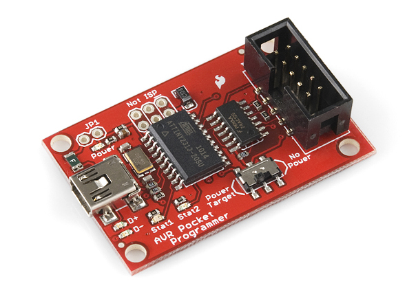
For a quick easy programmer we recommend looking into the AVR Pocket Programmer (Windows only).
pocket programmer
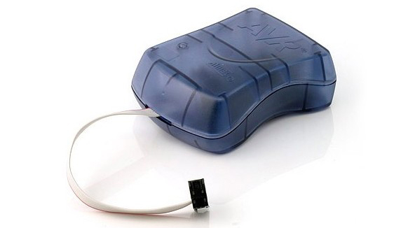
Or, you can use the official Atmel AVR MKII programmer or the Atmel JTAG ICE3 programmer.
AVR MKII
The AVR Pocket Programmer or most cheaper options will work just fine for most applications, but they may have problems with some boards, specifically ones with lots of memory like the ATMega2560 based boards.

Option 2: Using the Arduino as a Programmer
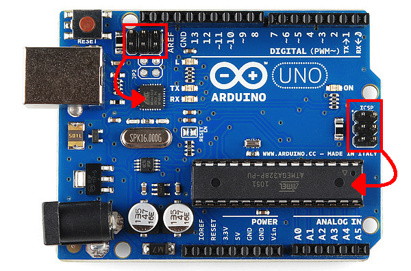
The other option is grabbing an Arduino Uno (or Duemilanove). If you go into the Arduino IDE you will see an example sketch called ‘Arduino as ISP.’ If you upload this code to your Arduino, it will basically act as an AVR programmer. This isn’t really recommended for production of boards, or boards with lots of memory, but, in a pinch, it works pretty well. Also as of this writing the code only works on ATmega328 boards. Maybe one day it will work on the Leonardo or Due, but not yet.

In-Circuit Serial Programming (ICSP)
It’s very uncommon to program ICs before they are soldered onto a PCB. Instead, most microcontrollers have what’s called an in-system programming (ISP) header. Particularly, some IC manufacturers, such as Atmel and Microchip, have a specialized ISP method for programming their ICs. This is referred to as in-circuit serial programming (ICSP) Most Arduino and Arduino compatible boards will have a 2x3 pin ICSP header on them. Some may even have more than one depending on how many ICs live on the PCB. It breaks out three of the SPI pins (MISO, MOSI, SCK), and power, ground, and reset. These are the pins you’ll need to connect your programmer to in order to reflash the firmware on your board.
UNO ISP
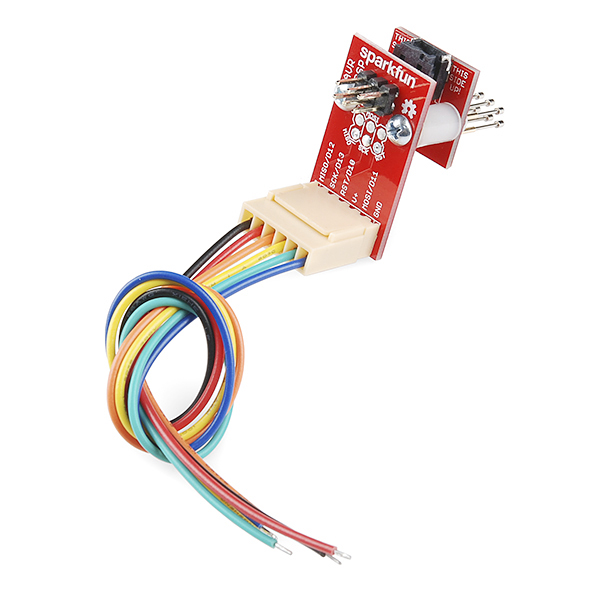
On some smaller boards you may not see this connector, but the pins should be broken out elsewhere. Whether you’re using anSMD IC or a DIP IC, the ISP pins should be accessible in one form or another. Some boards might only have test points for the ISP header. If this is the case, you may want to consider getting an ISP Pogo Adapter. This kit allows you to temporarily make a good connection with test test points in order to reprogram your IC.
alt text
If you are having trouble finding the ICSP pins on your particular Arduino board, you can consult this website for detailed pinouts of most Arduino related ICs and then some.
Once you have located the six ICSP pins on your board, it’s time to hook up your programmer to the board. You can use aprogramming cable to connect the two, or, if you don’t have a cable, you can just use some male-to-female jumper wires.

2016年11月28日星期一

Clap Switch Circuit Electronic Project Using 555 Timer

Introduction

Clap Switch is a basic Electronics mini-project, made with the help of the basic components. Clap Switch has the ability to turn ON/OFF any electrical component or circuit by the clap sound.
It is known as Clap Switch, because the condenser mic which will be used in this Project will have an ability to take the sound having same pitch as the Clap sound as the input. Although it doesn’t mean that the sound will have to be of Clap sound, it can be any sound having the same high pitch as of Clap. We can also say that it converts the Sound energy into the Electrical Energy, because we are giving an input to the circuit as a sound whereas the Circuit gives us the output as a LED glow (Electrical Energy).

Required Components

As already mentioned, this project is basic Electronics mini-project, so this project is made of the basic components. Following is the list of the components required to make the Clap Switch.
1.1K, 4.7K, 47K, 330 and 470 ohm resistors
2.10µF and 2 100nF capacitors
3.Electric Condenser mic
4.Two BC547 transistors
5.LED
6.555 timer
7.9V Battery


Simple Wav Player Using Arduino

Overview

Integrated with the homemade low-pass filter, this Arduino-based simple WAV player is to send out PWM signal generated by UNO, then through the low-pass filter and make the PCM data stored in the flash of UNO into sounds. Basically, the player cannot be regarded as a pure WAV playback, because by extracting the data from the WAV file and storing it in an array format in UNO, this tutorial is for reference. You can make SD card based WAV player by referring to this idea. The WAV player is easy to make on different platforms and applicable for various scenarios like voice broadcast system, electronic keyboard, as long as you understand the principle of sound.

Prepare
The hardware:
1.USB mini speaker
2.Digital push button
3.Freaduino UNO
4.4×6 cm universal board
5.Dupont line
6.Audio port

more imformation-----http://www.tenco-tech.com/article.php?id=94


Electronic Components Importer and Supplier


We are an electronic components trading company from China.Tenco Technology-Electronic Components Importer and Supplier.We have professional electronic material engineer to provide technical support.To provide electronic components supporting services for electronic manufacturer,including electronic components,wire and cable,plugin/SMD LED,capacitance,resistance ect.Service customers from all over the world.Customers in need can consult.Website:http://www.tenco-tech.com.Service mail :tenco-tech@outlook.com.Skype:sales03_101